VCAP6-CMA Deploy - Objective 3.1: Configure and Manage NSX Integration with vRealize Automation
vRealize Automation VCAP6 VCAP6-CMA NSX-V
Published on 11 February 2017 by Christopher Lewis. Words: 1669. Reading Time: 8 mins.
Objective 3.1 - Configure and Manage NSX Integration with vRealize Automation
Objective Overview
- Implement machine blueprints that use:
- External network profiles
- Routed network profiles
- NAT network profiles
- Private network profiles
- Deploy applications using a pre-configured networking model
- Deploy applications using a fully automated networking model
- Configure static and dynamic routing
- Deploy an application that uses an automatically provisioned load balancer
- Apply a security policy to elements of a multi-machine blueprint
- Automate the application of a security policy to new machines provisioned from a blueprint
Objective Prerequisites
The following prerequisites are assumed for this Objective:
- VMware vRealize Automation is fully deployed.
- VMware NSX is installed and integrated into vSphere.
- VMware NS Security Groups, Security Policy and Security Tags have been defined in VMware NSX.
Objective Breakdown
Implement machine blueprints that use Network Profiles (External, Routed, NAT and Private)
In this example, we’ll look at how to create a Network Profile and how to assign that Network Profile to a Reservation. Finally we’ll look at how, using Custom Properties, you can automatically assign a Network Profile to a Virtual Machine Blueprint.
External Network Profile
An External Network profile is one where the configuration is held externally to vRealize Automation, such as a Physical Network.
The creation of Network Profiles is the responsibility of the Fabric Administrator role.
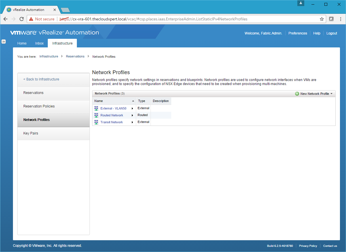
- Navigate to the vRealize Automation Tenant Portal, log in with a user that has the Fabric Administrator role assigned and navigate to Infrastructure > Reservations > Network Profiles.
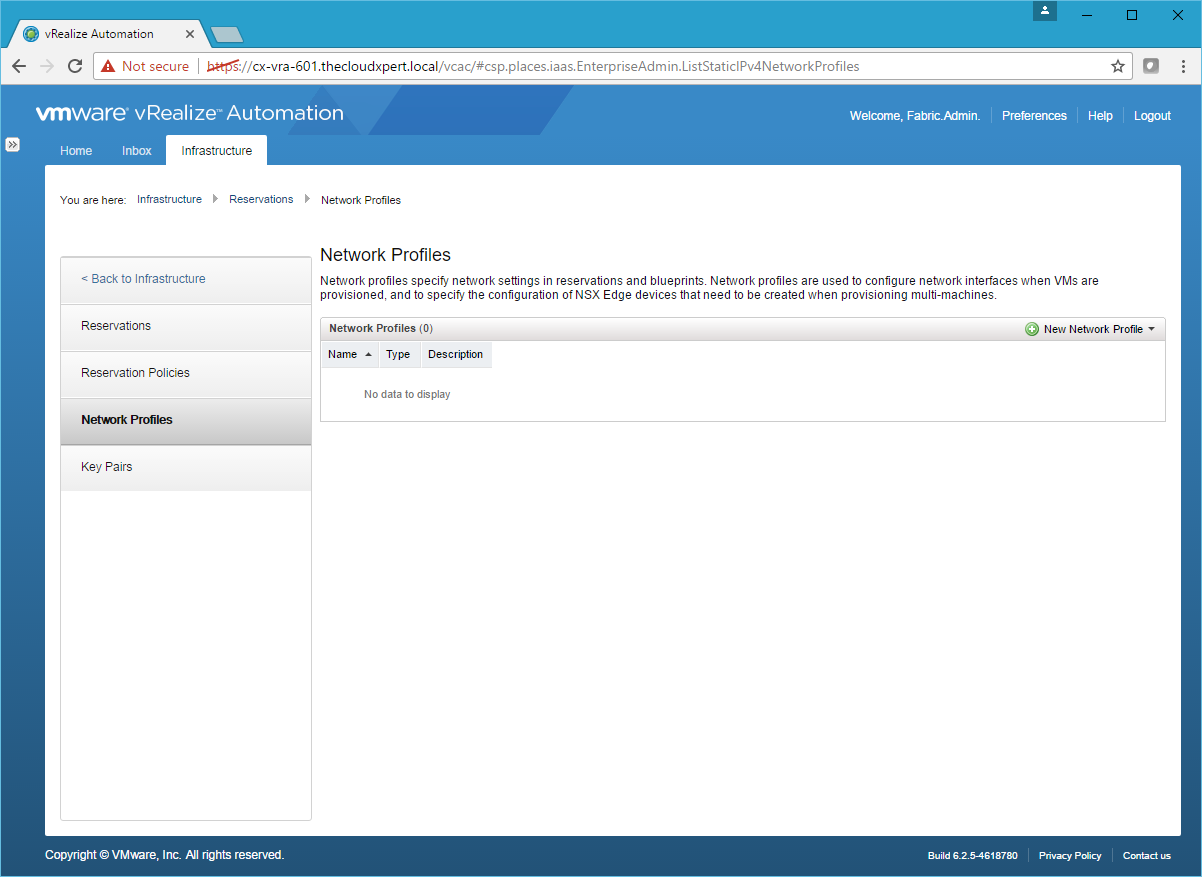
- Click New Network Profile > External.
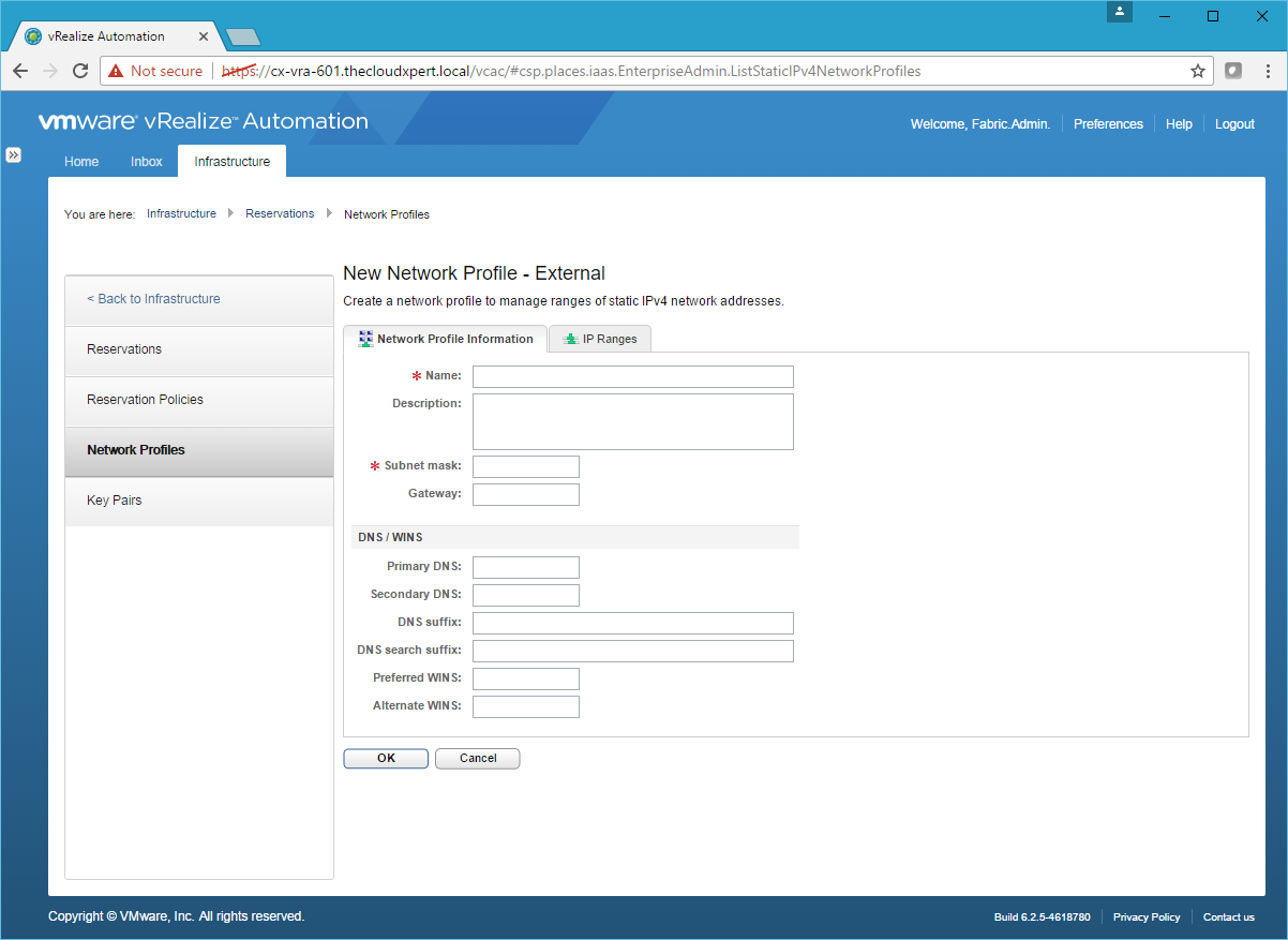
- Type the Name of the External Profile, Subnet Mask, Gateway and (optional) DNS Server.
- Click the IP Ranges Tab.
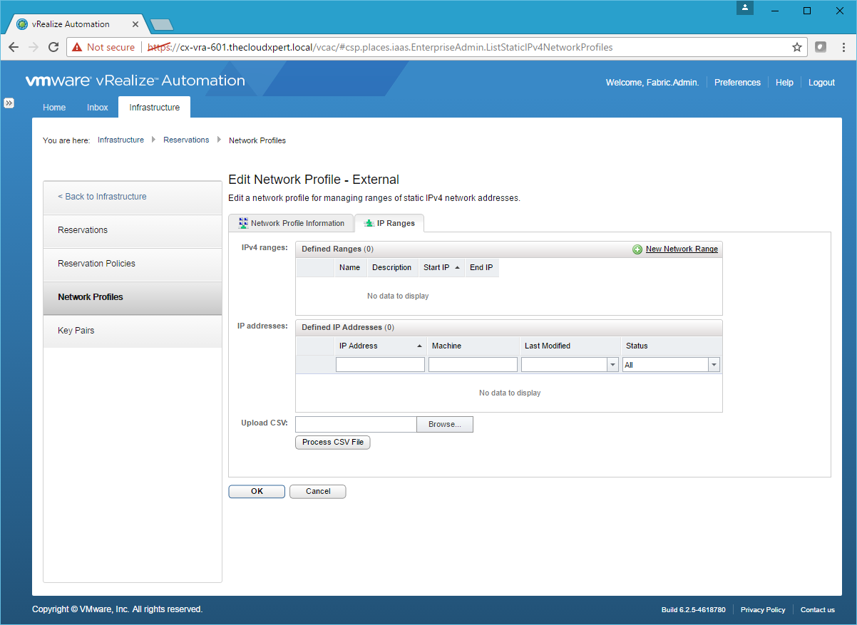
- Click New Network Range.
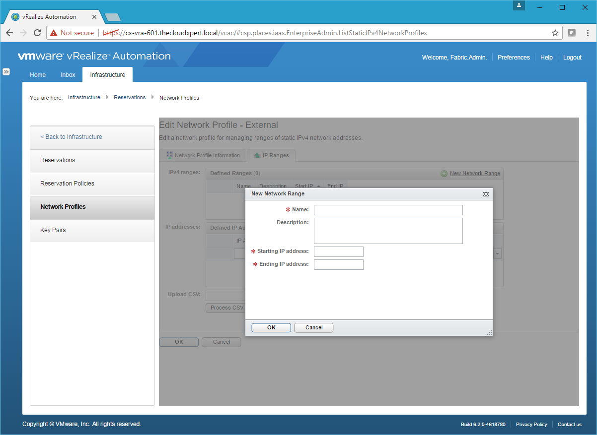
- Type the Name, Starting IP address and Ending IP address and click OK.
- Click OK.
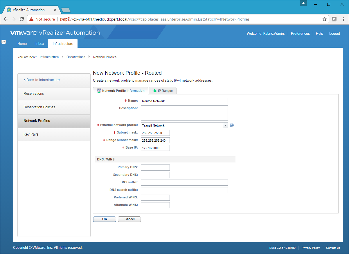
Routed Network Profile
- Click New Network Profile > Routed.
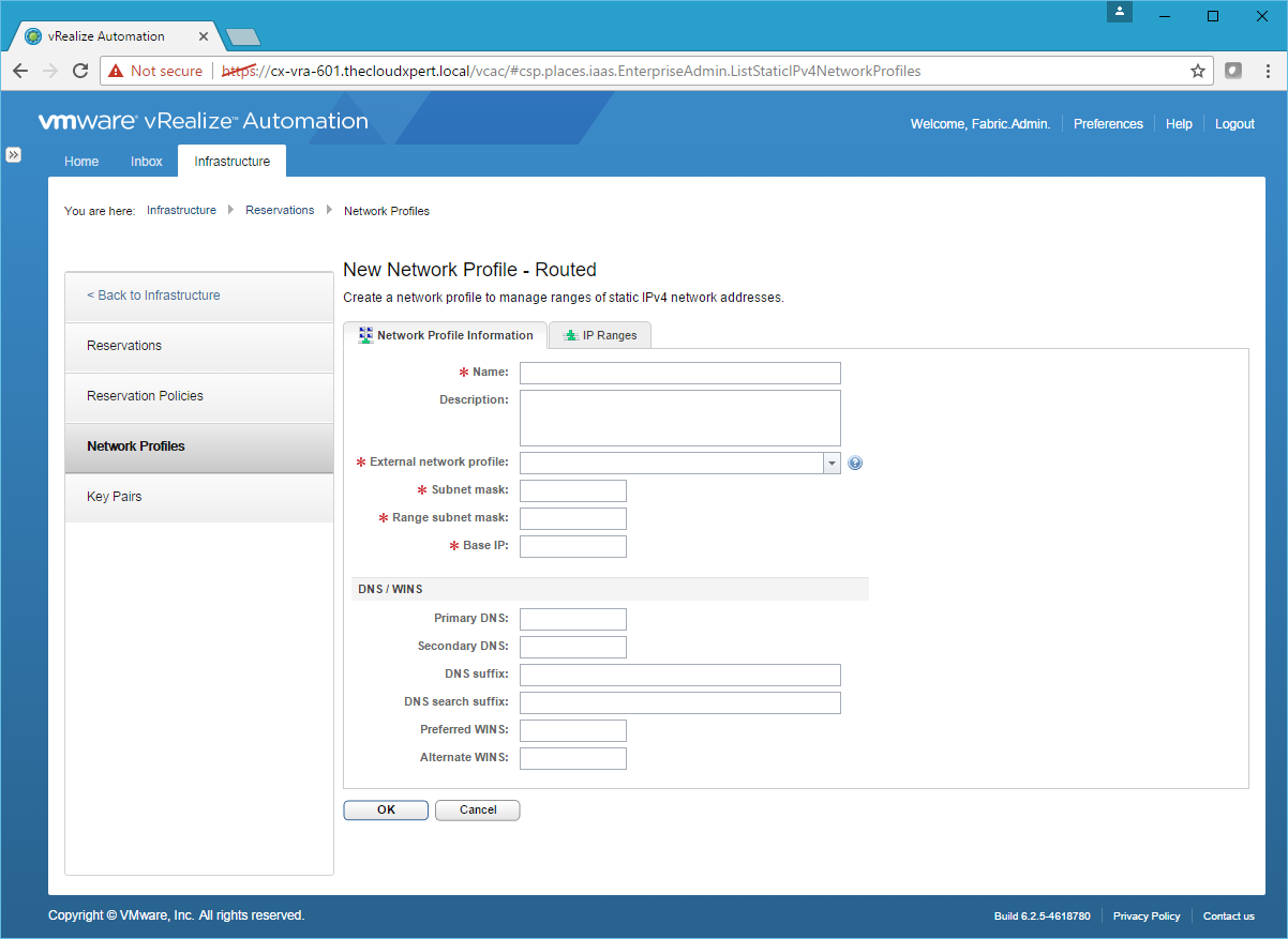
- Enter the Name, select an External Network Profile, enter a Subnet mask, a Range subnet mask and a Base IP.
- Click the IP Range Tab.
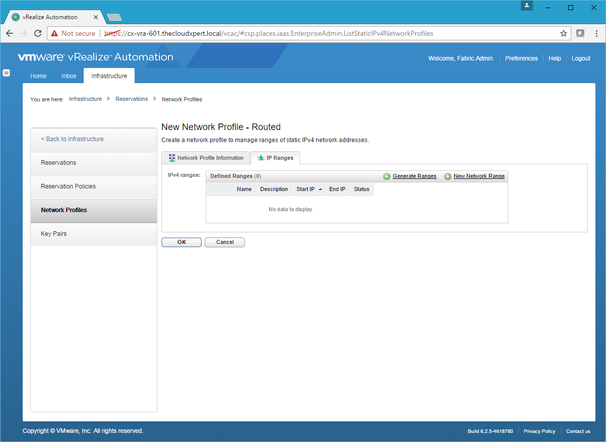
- Click Generate Ranges.
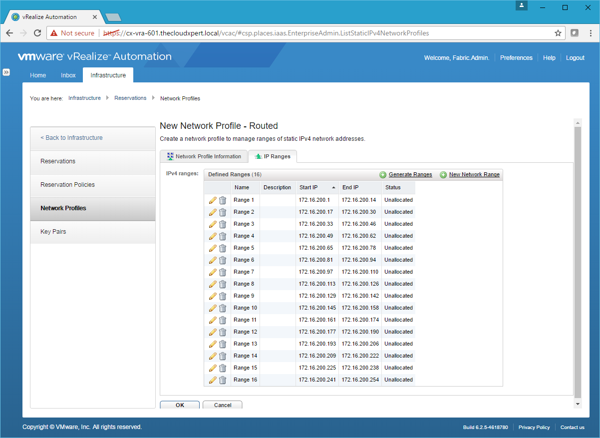
- Click OK.
NAT Network Profile
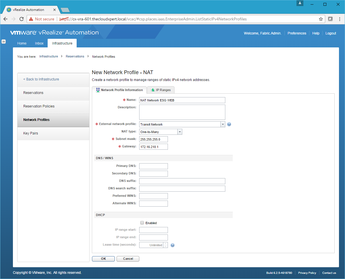
- Click New Network Profile > NAT.

- Type the Name, select the Transit Network as the External network profile, select the One-to-Many as the NAT Type, enter the Subnet mask and the Gateway address.
- Click the IP Ranges Tab.
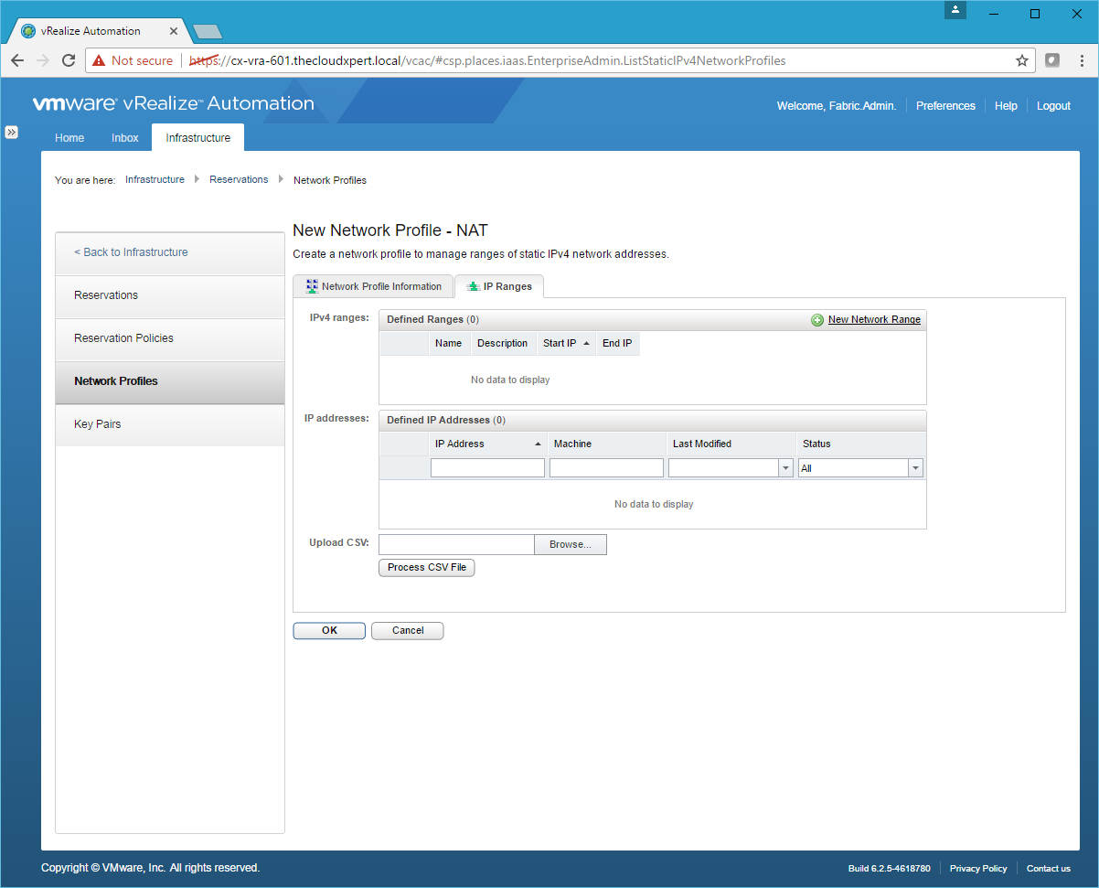
- Click New Network Range.
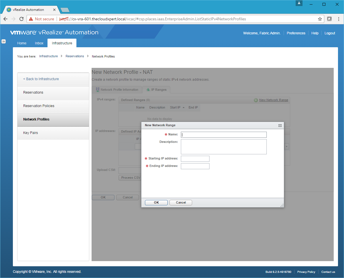
- Enter a Name, Starting IP address and Ending IP address for the Network Range and click OK.
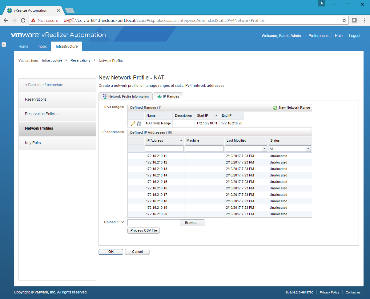
- Click OK.
Private Network Profile
- Click New Network Profile > Private.
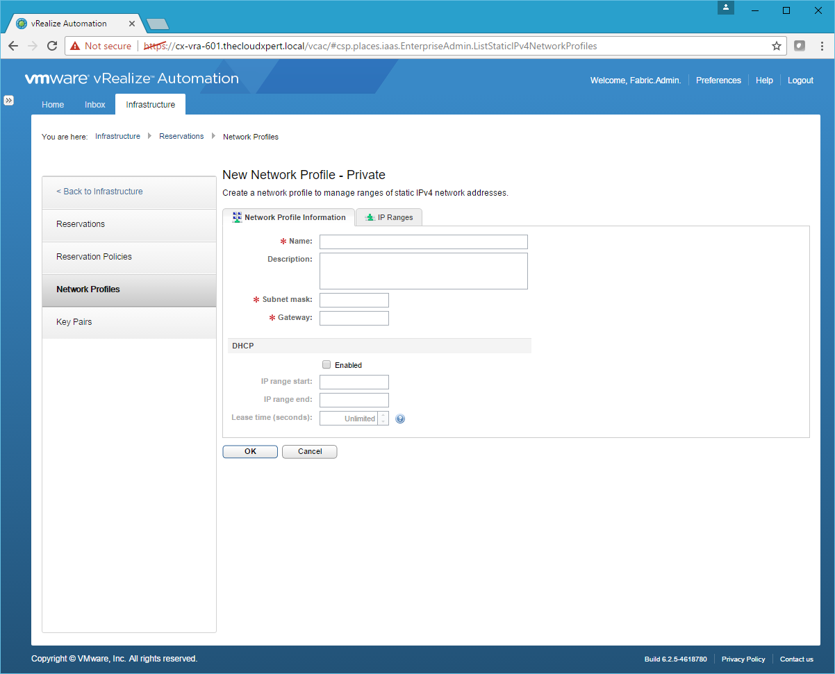
- Type the Name, enter the Subnet mask, and the Gateway address.
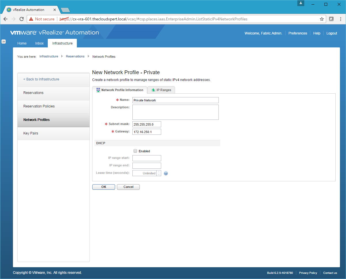
- Under DHCP, Click the Enable checkbox and enter values for the IP Range Start and IP Range End.

- Click OK.
Assigning Network Profiles to a Reservation
For a Routed Network we need to update the Compute Reservation with the Transit Network.
- Navigate to Infrastructure > Reservations > Reservations.
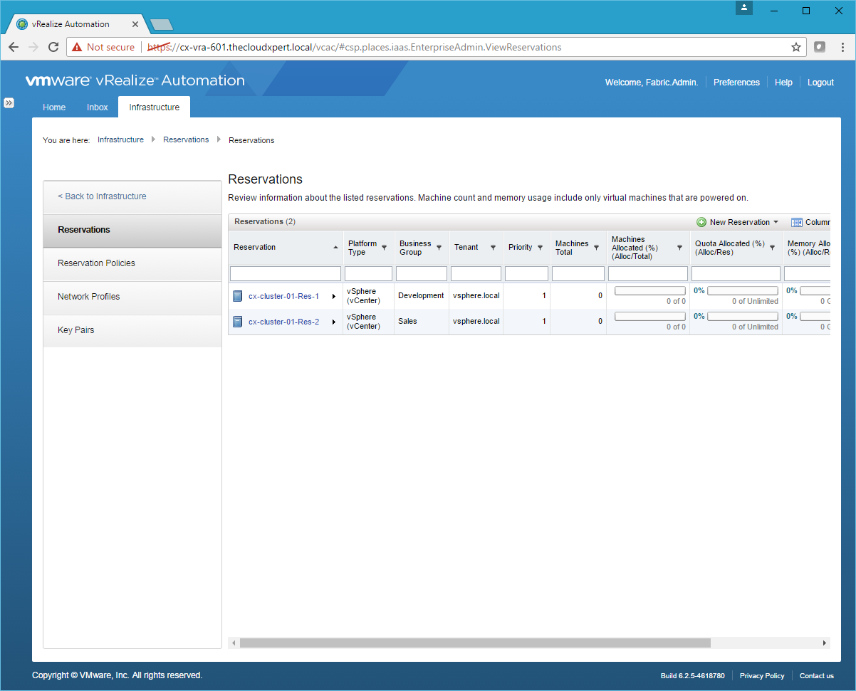
- Click on the Reservation to be updated.
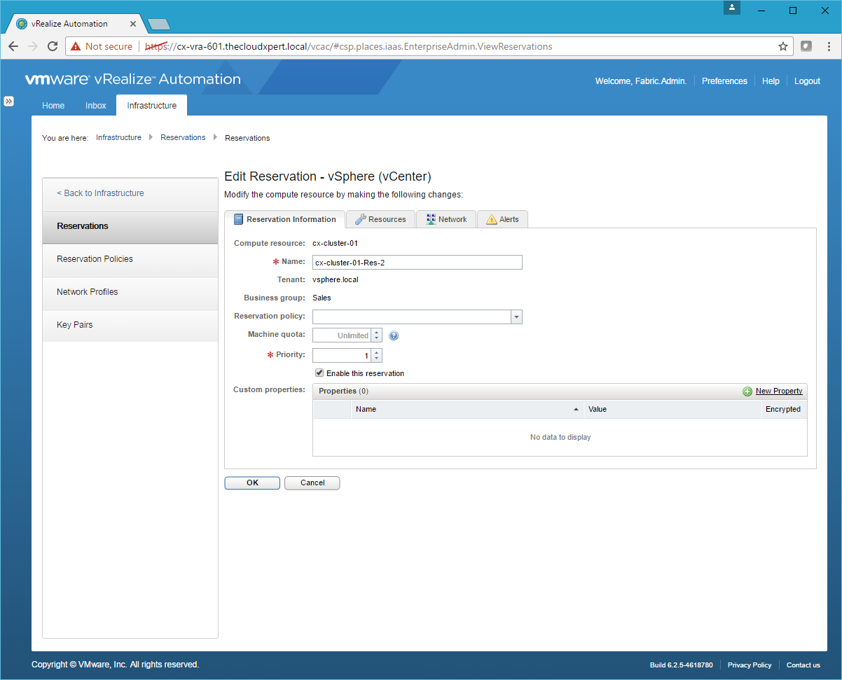
- Click the Network Tab.
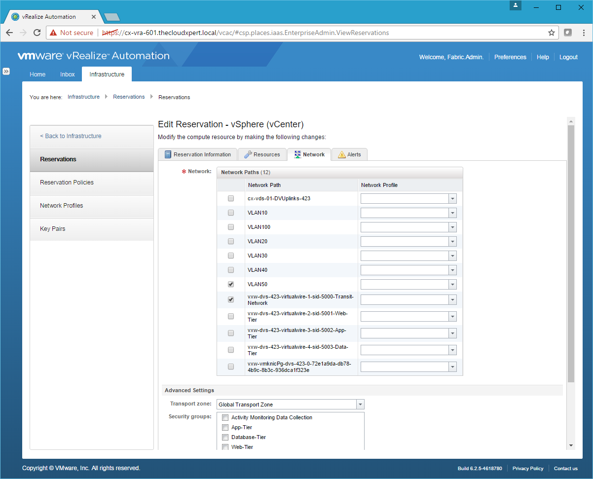
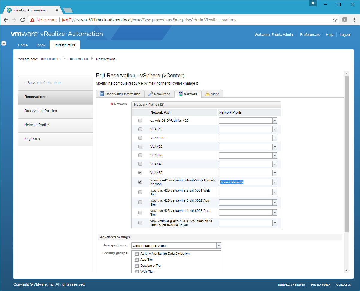
- Check the Transit-Network Network Path and then select the Transit Network from the Network Profile drop down.
- Scroll down to the bottom of the page and check the Routed Gateway.
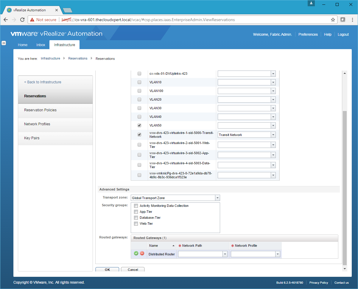
- Choose Transit-Network from the Network Path drop down and Transit Network from the Network Profile drop down.
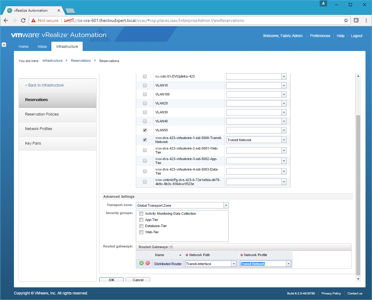
- Click Save and then click OK.
Deploy applications using a pre-configured networking model
I believe this is asking you to create a Multi-Machine blueprint but deploy to traditional External Networks (VLANS) that may already exist in the physical world.
For a N-Tier architecture, the process is:
- Create the External Network Profile for each VLAN.
- Create a Multiple Machine Blueprint with all the components in.
So if we assume we have completed Step 1 is completed. Let us walk through the creation of a Multi-Machine blueprint with 3 Tiers.
- Navigate and Log into the vRealize Automation Tenant Portal as a user with the Tenant Administrator and/or Business Group Manager role assigned.
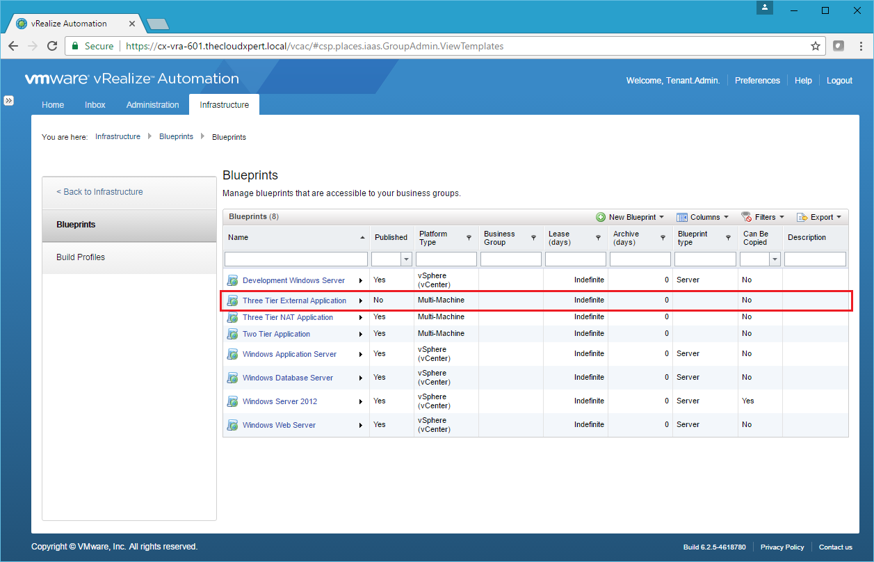
- Navigate to Infrastructure > Blueprints > Blueprints.
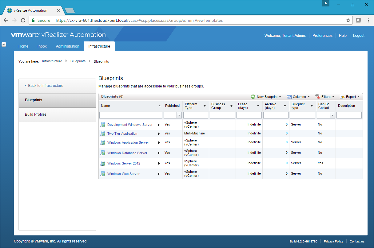
- Click New Blueprint > Multi-Machine.
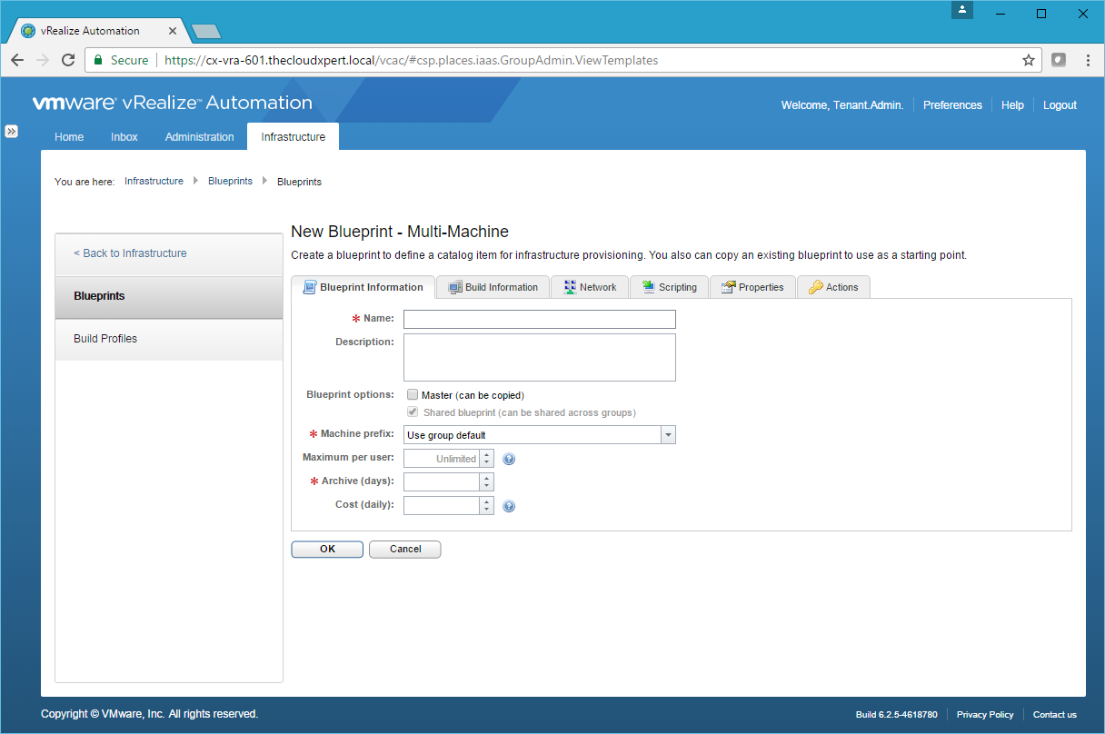
- Type the name of the blueprint into the Name field, select a prefix (or leave Use group default) from the Machine Prefix dropdown and enter a value into the Archive field.
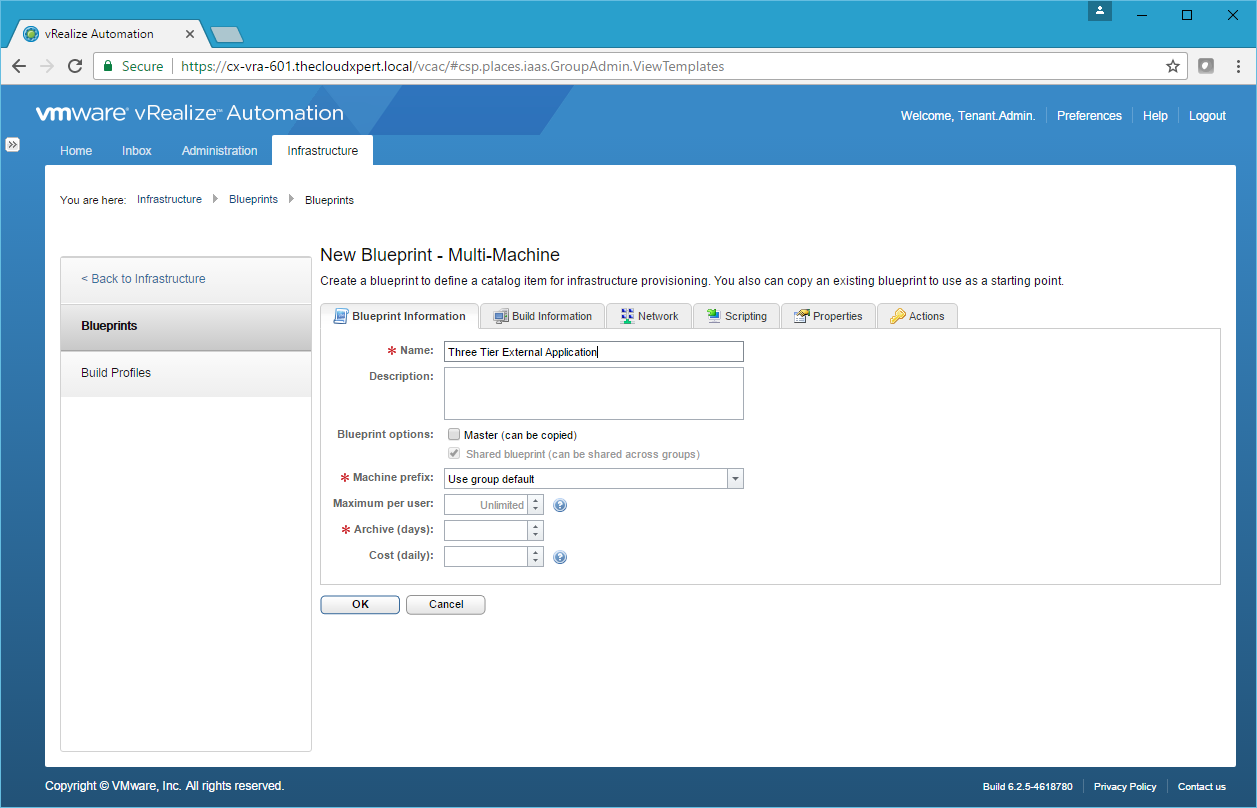
- Click the Build Information tab.
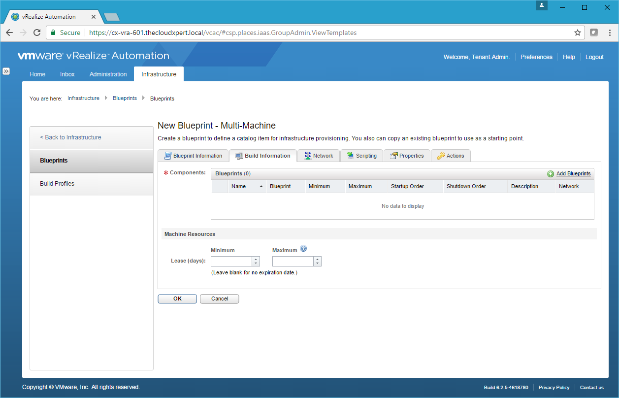
- Click Add Blueprints.
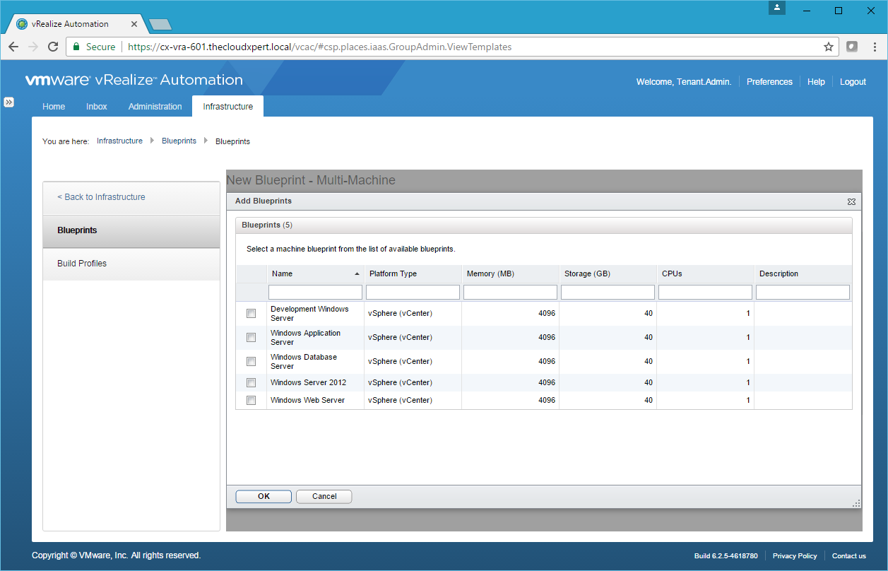
- Check the checkbox next to each of the Blueprints to add to this Multi-Machine blueprint and click OK.
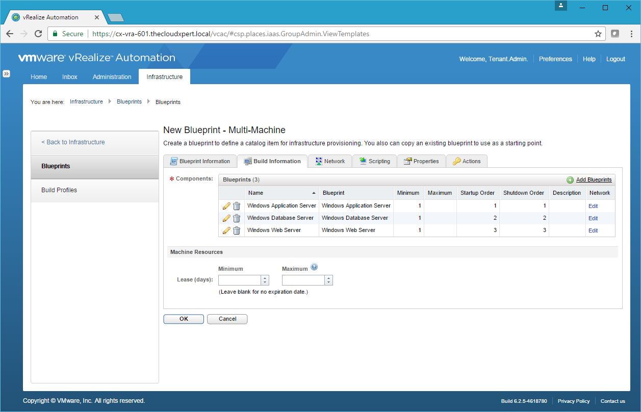
- If required, click Edit (Pencil) next to each Component Blueprint to make any changes to the Minimum or Maximum number of VMs to be deployed and the Startup and Shutdown Order.

- For the first Component Blueprint, click Edit under the Network Column.

- Click New Network Adapter.

- Select the appropriate Network Profile from the Network Profile dropdown and then click Save.
- Add additional Network Adapters if required and then click OK.
- Complete the previous steps for each of the Component Blueprints so they have at least 1 Network Adapter each and then click OK.
And there we have a basic 3 tier Multi-Machine Blueprint using the traditional network architecture in vSphere.
Deploy applications using a fully automated networking model
I believe this is asking you to create a Multi-Machine blueprint with NSX and either a multi-tier NAT, multiple tier Routed or single routed network with Security Groups.
For a N-Tier architecture, the process is:
- Create the External Network Profile for the Transit Network.
- Create the NAT (or Routed) Network Profile(s) for each of the Tier of the Application (e.g. Web, App, Data)
- Create a Multiple Machine Blueprint with all the components in it.
So if we assume we have completed Step 1 and Step 2 (following the information in the start of this post) and we also assume we have the Blueprints ready to use for each tier. Let us walk through the creation of a Multi-Machine blueprint with 3 Tiers and NAT.
- Navigate and Log into the vRealize Automation Tenant Portal as a user with the Tenant Administrator and/or Business Group Manager role assigned.
- Navigate to Infrastructure > Blueprints > Blueprints.
- Click New Blueprint > Multi-Machine.
- Enter the name of the blueprint into the Name field, select a prefix (or leave Use group default) from the Machine Prefix dropdown and enter a value into the Archive field.

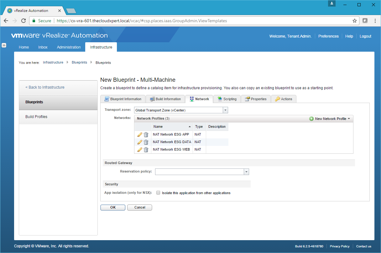
- Click Network tab.

- Select the appropriate Transport Zone from the Transport Zone dropdown.
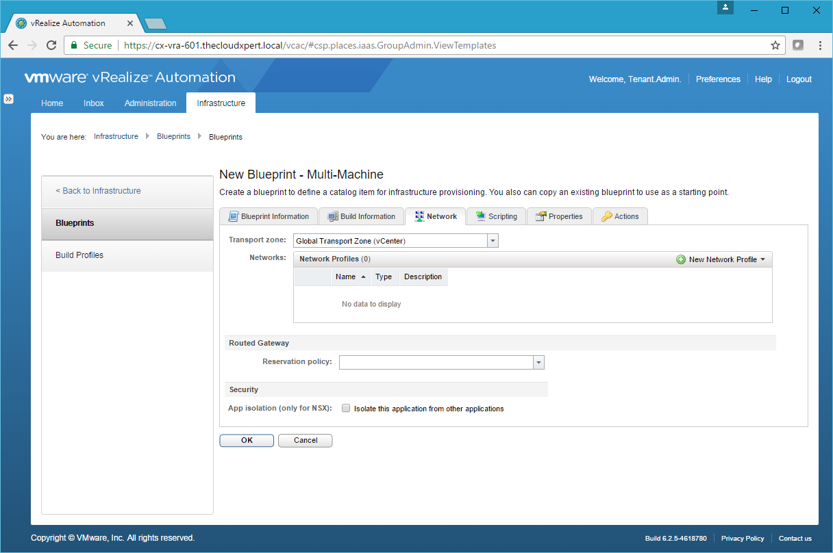
- Click New Network Profile > NAT.
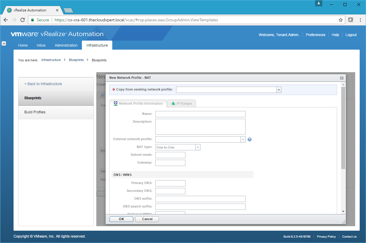
- Use the Copy from existing network profile dropdown to select the Network Profile to copy.

- Make any necessary changes and then click OK.

- Complete the steps again to add as many Network Profiles as is required.
- Click the Build Information Tab.
- Click Add Blueprints.
- Check the checkbox next to each of the Blueprints to add to this Multi-Machine blueprint and click OK.

- If required, click Edit (Pencil) next to each Component Blueprint to make any changes to the Minimum or Maximum number of VMs to be deployed and the Startup and Shutdown Order.

- For each Component Blueprint, under Network click Edit.
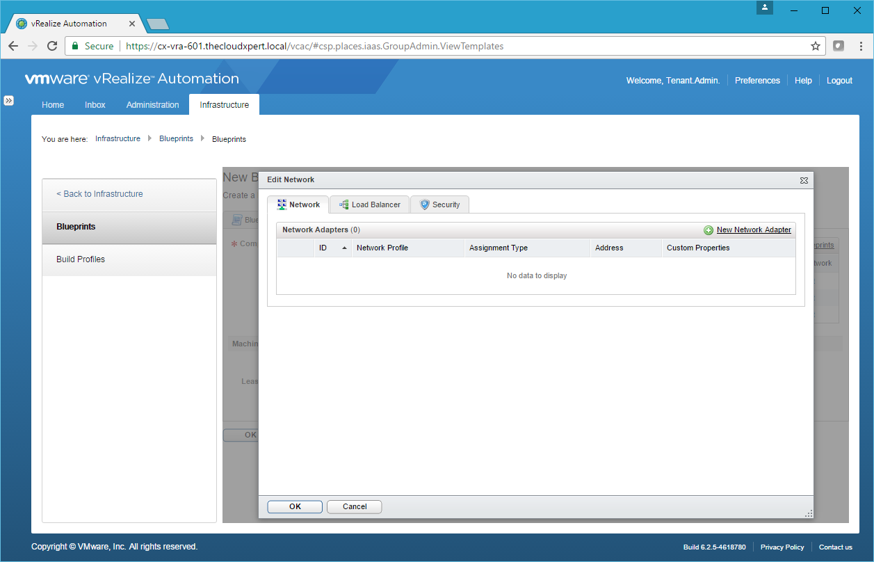
- Click New Network Adapter.

- Select the appropriate Network Profile from the dropdown and click Save.
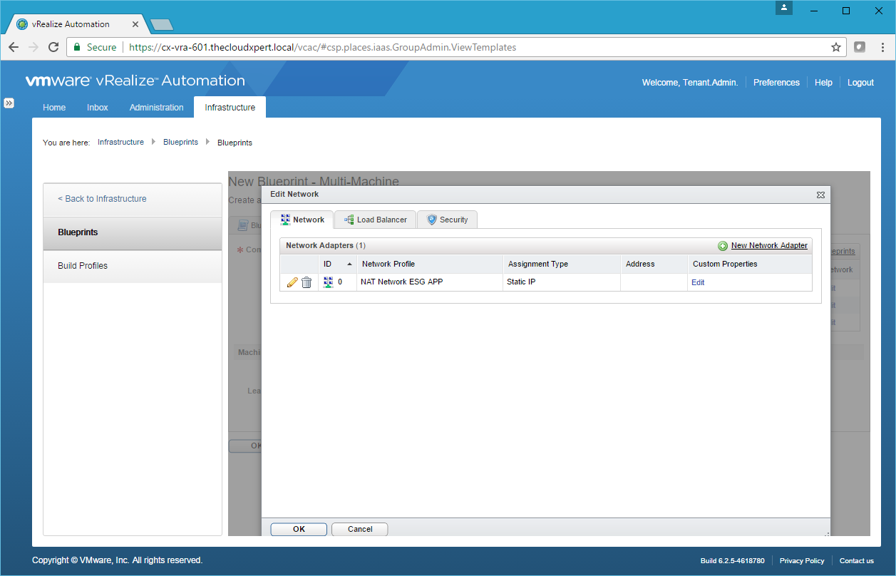
- If required/desired, click Edit under Custom Properties to add/edit Custom Properties, then click OK.
- You will need to add at least 1 Network per Component Blueprint - otherwise how will they communicate?
- You can now optionally add Custom Properties, Actions or Scripting to the Multi-Machine Blueprint, but we don’t need to.
- Click OK.
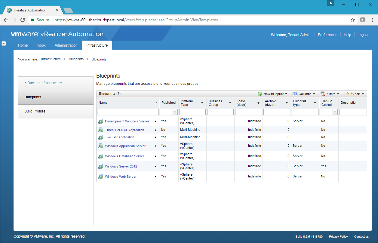
- Hover over the new Blueprint and click Publish.
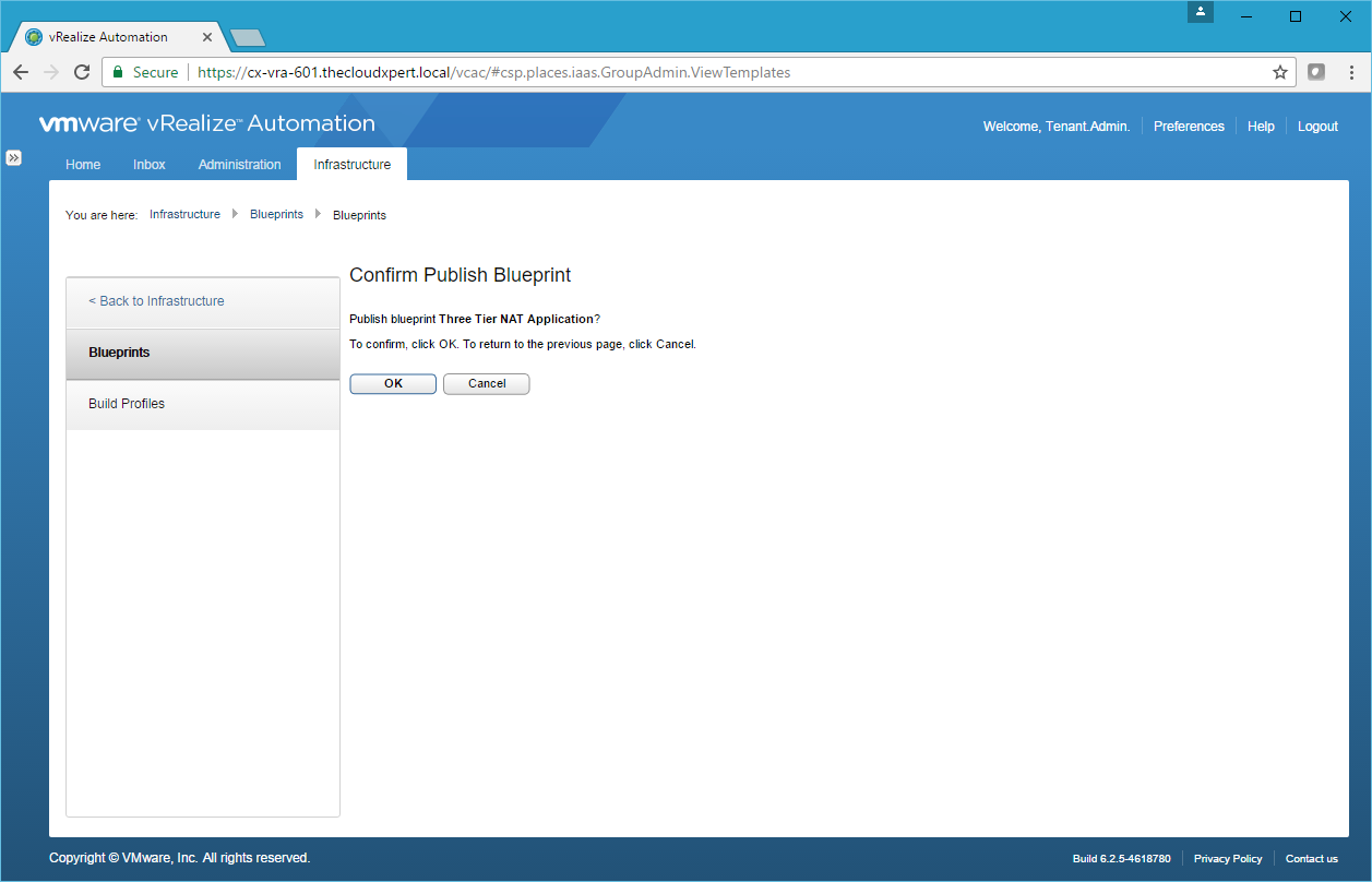
- Click OK.

Configure Static Routing
Static routing needs to be configured on the NSX Edge Service Gateway and/ or Distributed Logical Router.
- Log into vCenter Server and navigate to Home > Network & Security > NSX Edges.
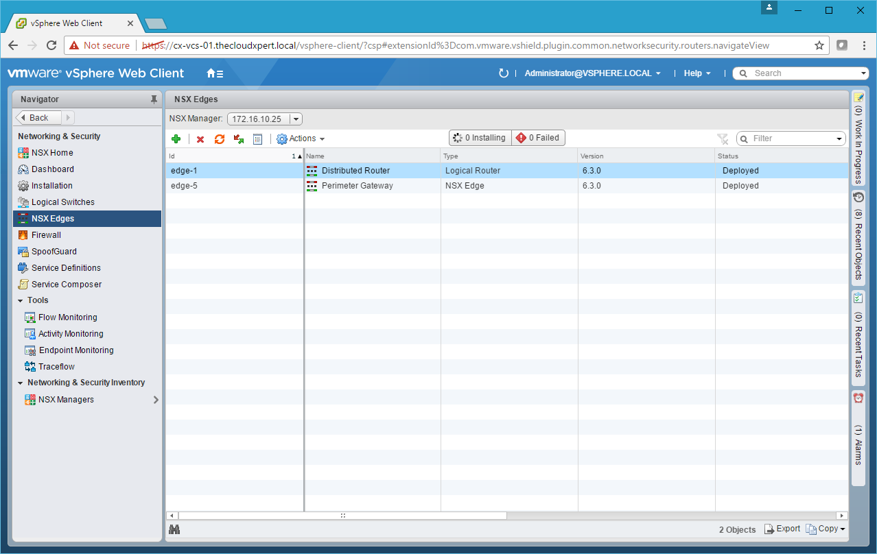
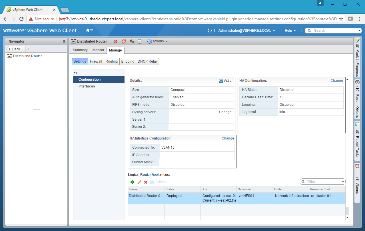
- Double-click on the Edge device you want to configure.
- Click Routing.
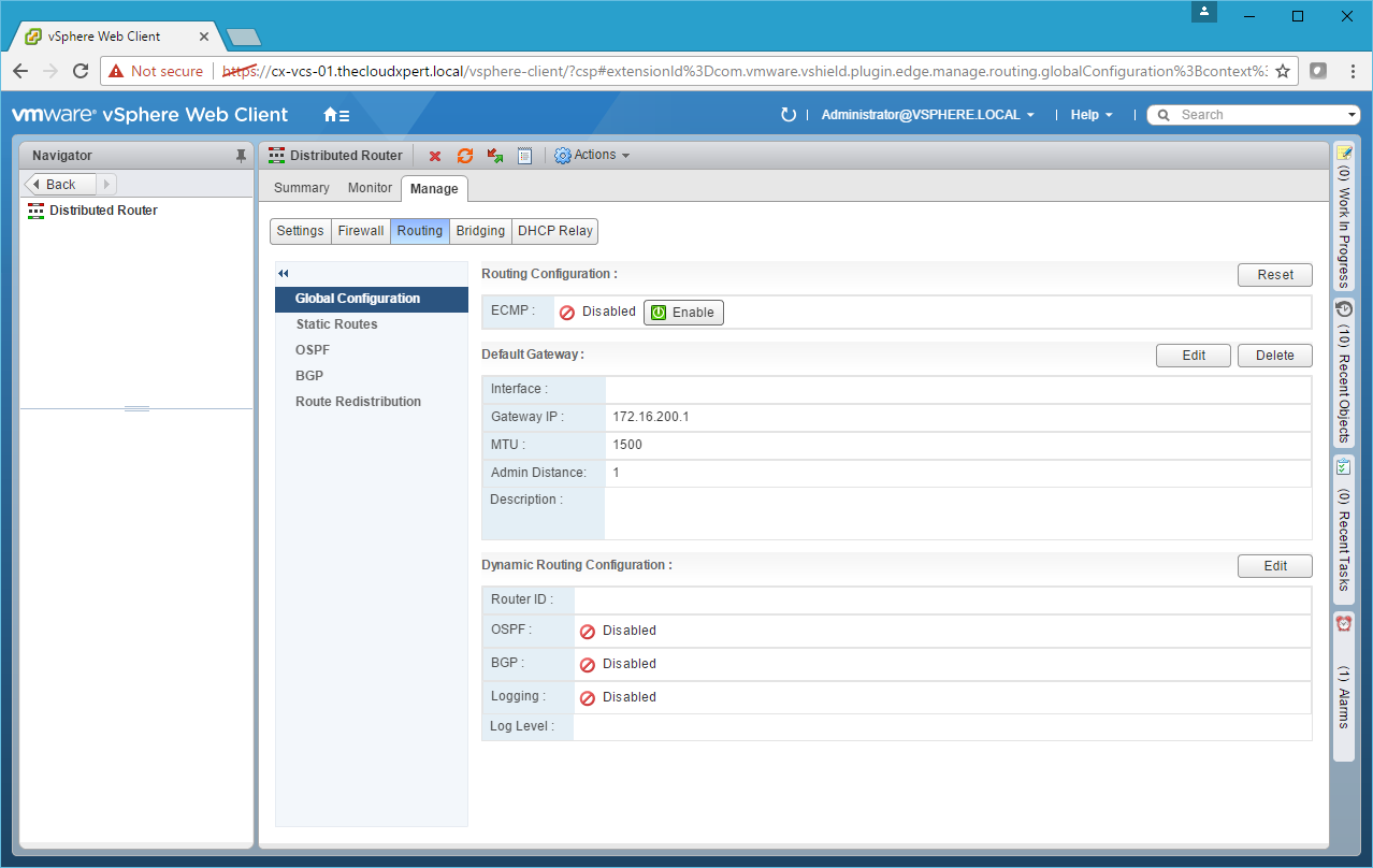
- Click Static Routes.
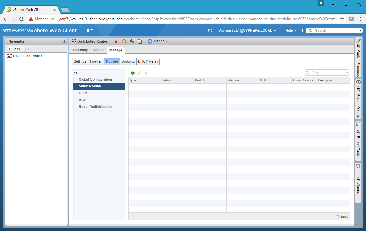
- Click Add(+).
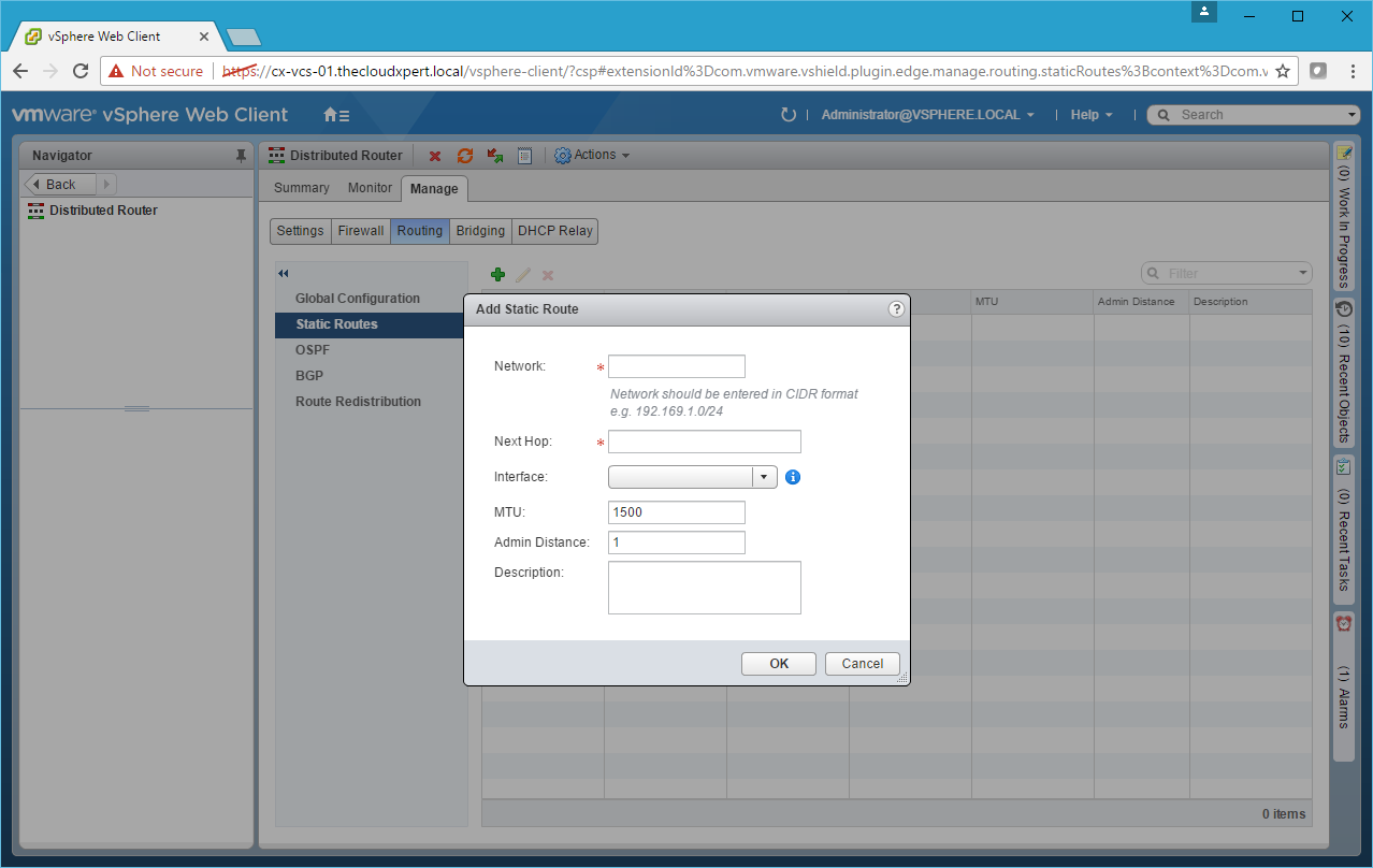
- Type the Network address Next Hop, select an Interface and then click OK.
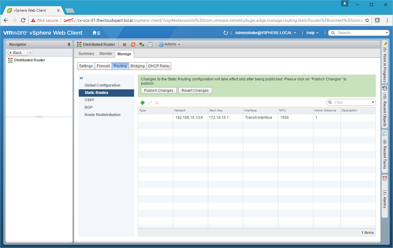
- Add any additional Static Routes required and then click Publish Changes.
Configure Dynamic Routing (OSPF)
Dynamic Routing needs to be configured on the NSX Edge Service Gateway and/or Distributed Logical Router.
See HOWTO: Configure VMware NSX with Dynamic Routing – BGP
See HOWTO: Configure VMware NSX with Dynamic Routing – OSPF
Deploy an application that uses an automatically provisioned load balancer
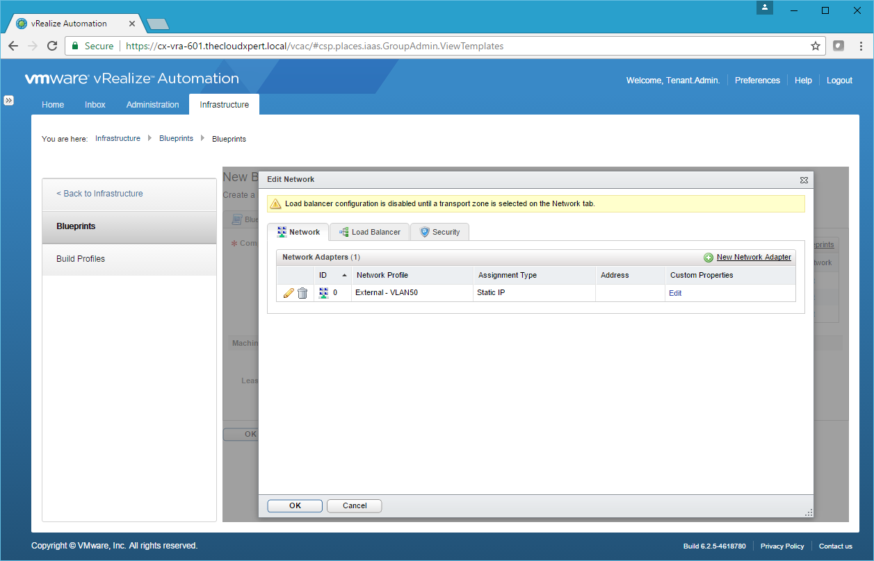
Adding Security Policy to a Component Blueprint, is completed when you add the Network Adapter onto the component.
- Click Load Balancer.

- Check the checkbox of the type service required.
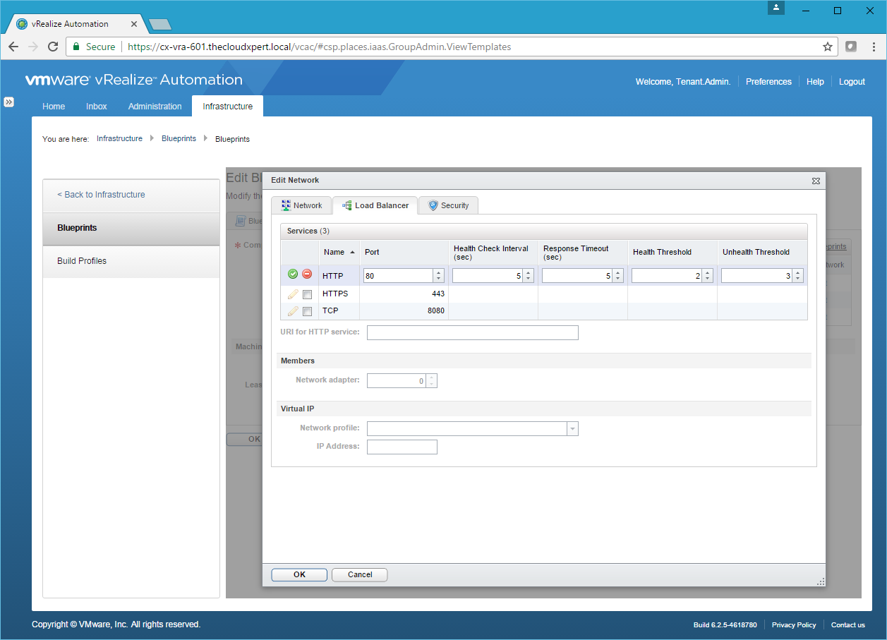
- Amend the Service details as required and then click Save.

- Optionally add a URI for HTTP Service, then select the ID of the Network Adapter to be used for Load Balancing, select the Network Profile to be used (if required add the IP Address) then click OK.
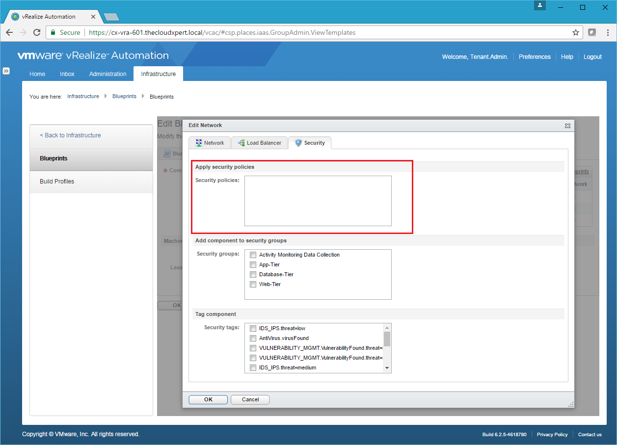
Apply a security policy to elements of a multi-machine blueprint
Adding Security Policy to a Component Blueprint, is completed when you add the Security Group onto the component.
Click the Security tab.
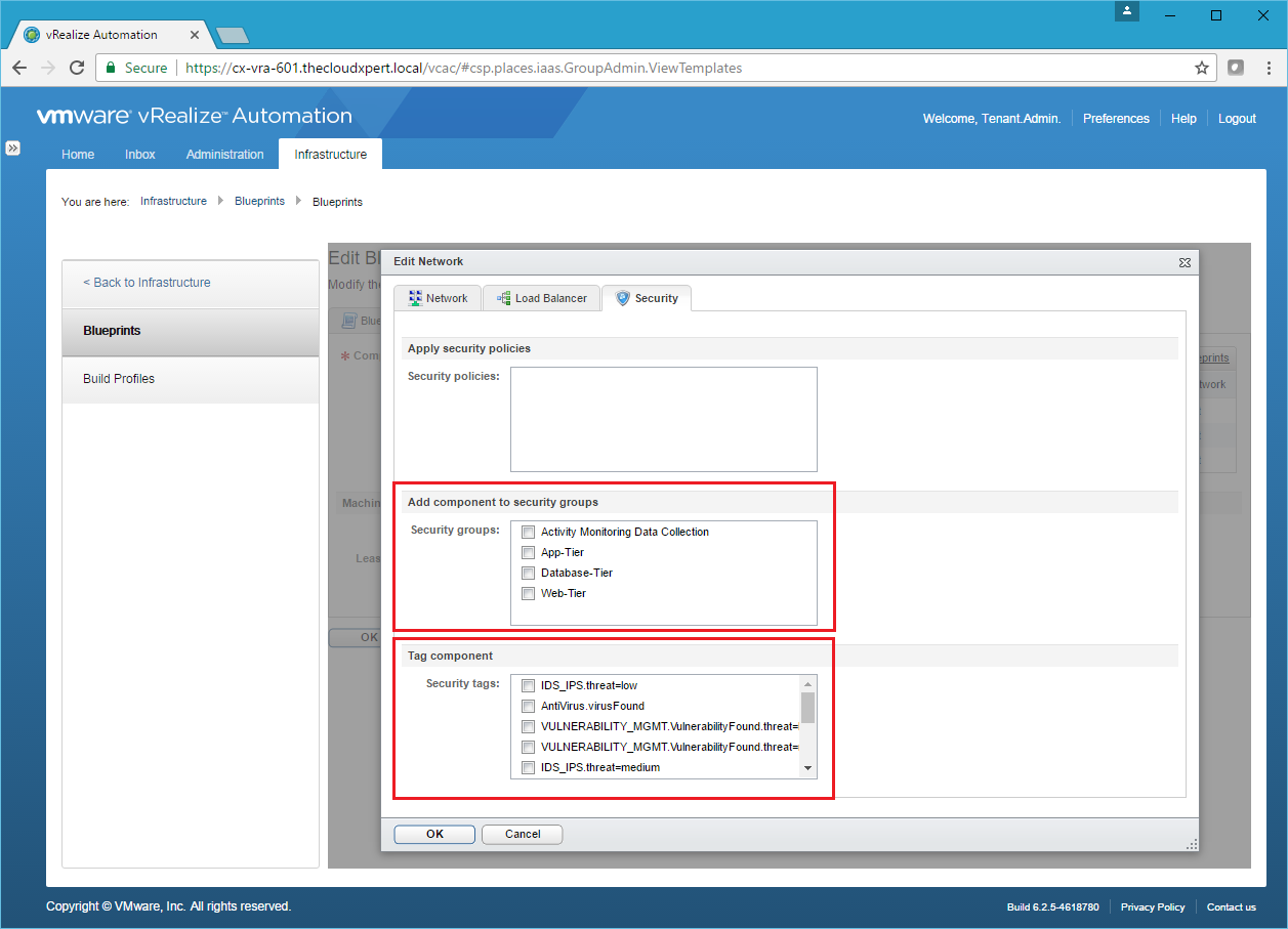
Automate the application of a security policy to new machines provisioned from a blueprint
I think this is all about create appropriate Security Groups (either based on dynamic membership such as server name or Security Tags) and Security Policies within NSX and then new machines being added automatically.
Assuming the Security Group already exists, you can add each Component Blueprint to one or more Security Group or assign a Security Tag to it so dynamic membership can occur.
Published on 11 February 2017 by Christopher Lewis. Words: 1669. Reading Time: 8 mins.
- VCAP6-CMA Deploy - Objective 4.4: Import existing workloads ()
- HOWTO: Configure a vRealize Automation 6 Advanced Services Endpoint for vCenter Server ()
- VCAP6-CMA Deploy - Objective 6.1: Configure Advanced Service Designer ()
- HOWTO: Configure a vRealize Automation 6 Advanced Services Endpoint for Active Directory ()
- VCAP6-CMA Deploy - Objective 5.2 - Modify a Blueprint to invoke a Workflow during a Lifecycle Change ()