HOWTO: Deploy a VMware NSX Distributed Logical Router (DLR)
VMware NSX-V VCAP6-NV VCIX6-NV HOWTO
Published on 31 July 2017 by Christopher Lewis. Words: 366. Reading Time: 2 mins.
This is one of many posts that will form part of the VCAP6-NV Deploy Exam Guide .
What is a Distributed Logical Router (DLR) ?
A Distributed Logical Router (or Logical Distributed Router) is typically used to route East/West traffic between Logical Switches.
In this example, we will create a new DLR with two Internal interfaces to connect the App_Tier and Data_Tier Logical Switches. FInally we’ll add an Uplink interface to connect the DLR to a “transit” logical switch.
Deploying a VMware NSX Distributed Logical Router (DLR)
_Note: Adding a DLR has a certain amount of prerequisites that can be found within the VMware Doc site here .
Note: These steps assume you are not even logged into vCenter Server. Skip the first few steps if you are!
Using your favourite web browser, navigate to the vCenter Server login page (https://vcenter.fqdn).
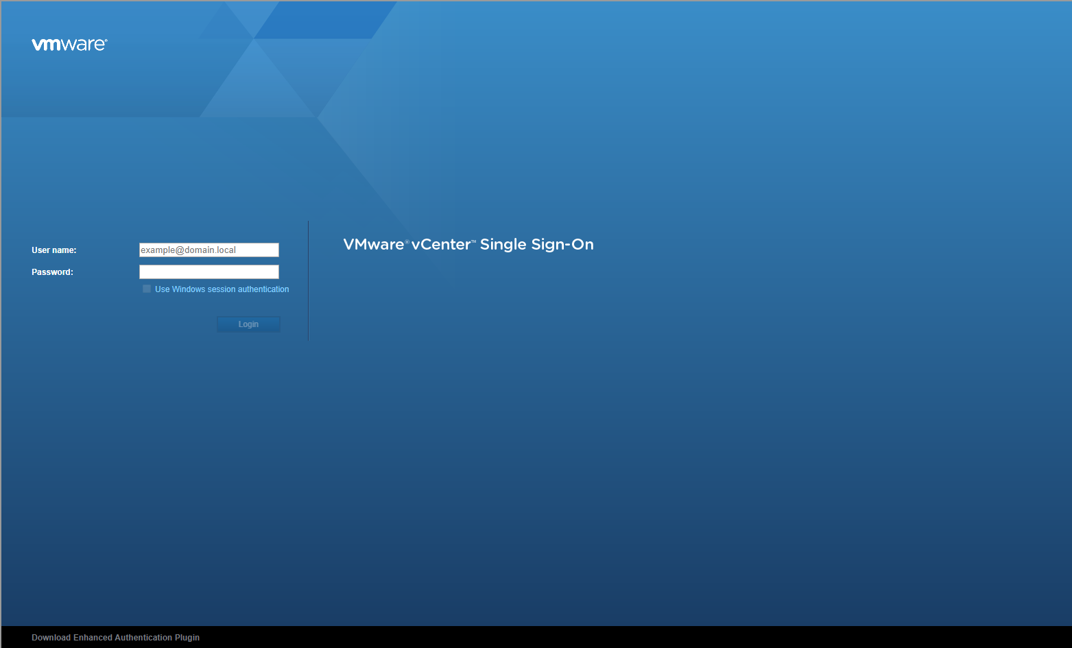
Enter appropriate User name and Password and click Login.
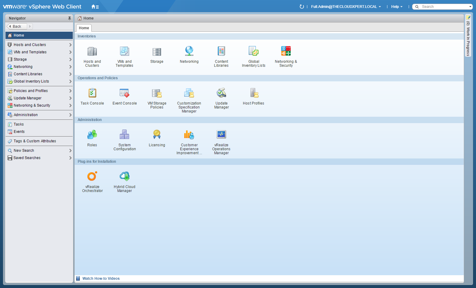
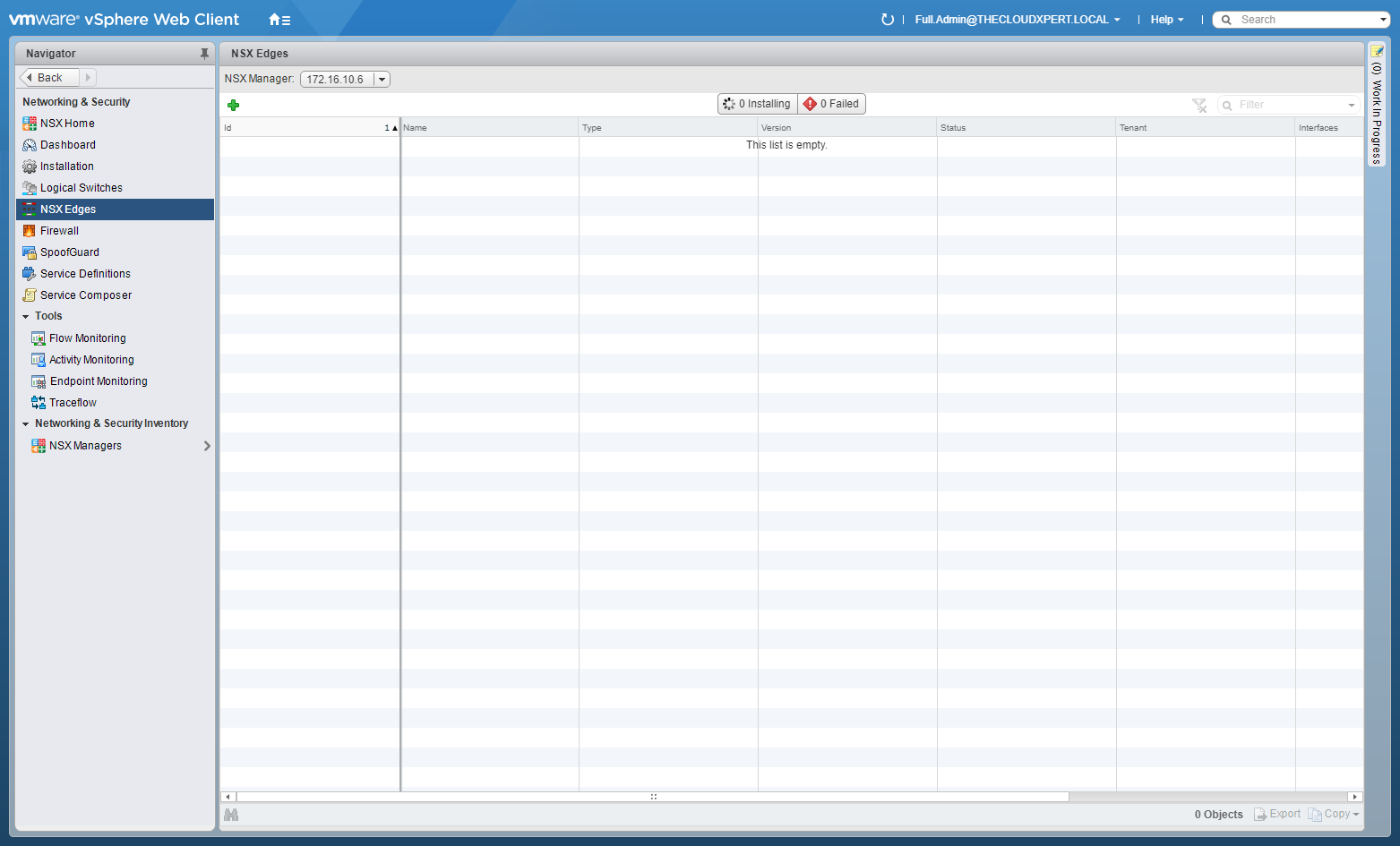
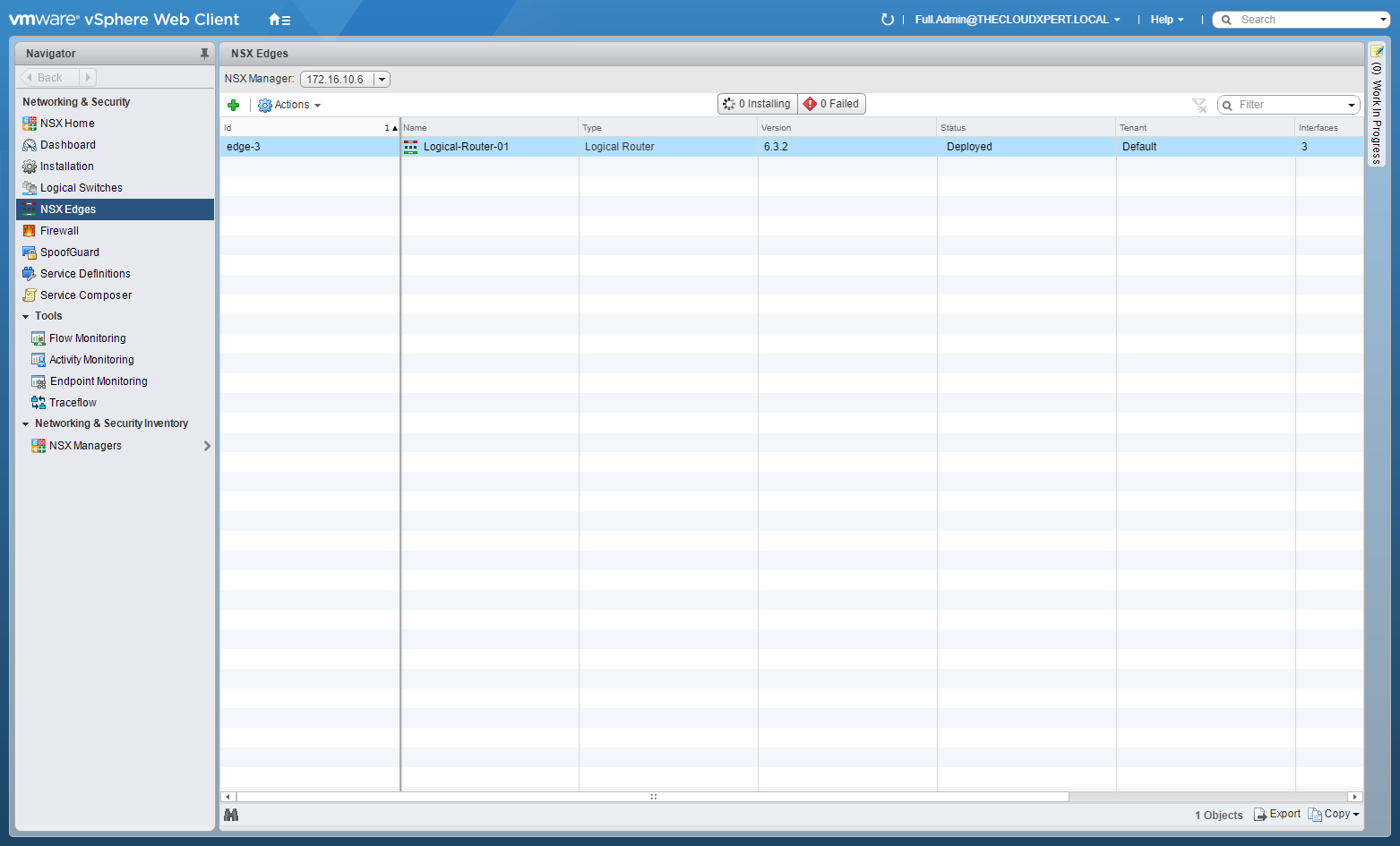
Click Network and Security.
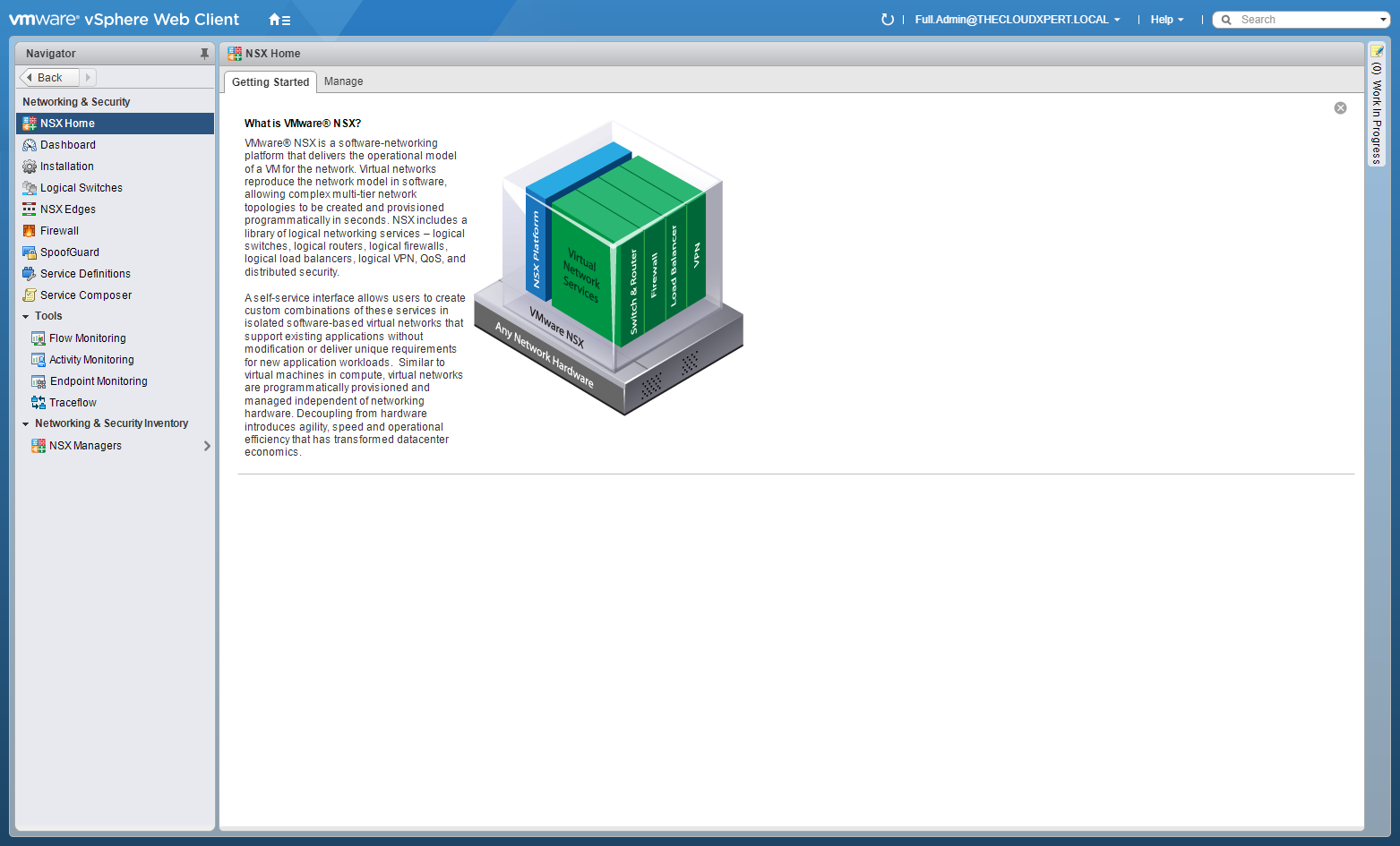
Click NSX Edges.
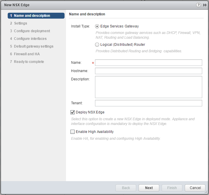
Select the Logical (Distributed) Router option.
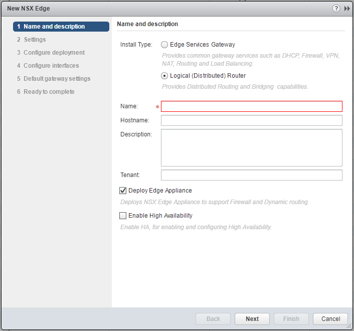
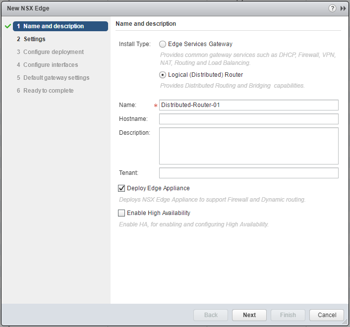
Enter a Name for the new Logical Router, (optionally) enter a Hostname, Description and Tenant. (Optionally) choose whether to check/uncheck the Deploy Edge Appliance and Enable High Availability checkboxes.
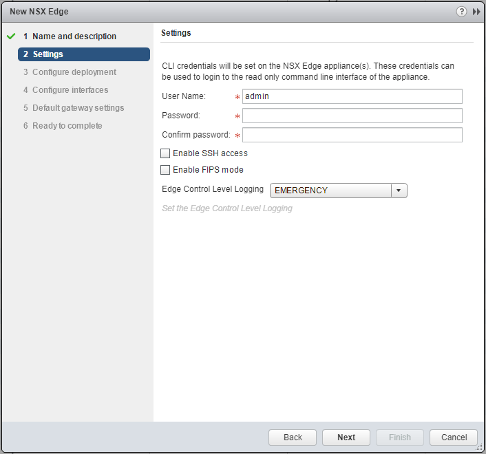
Enter and confirm a Password for the CLI credentials. (Optional) check the Enable SSH access or Enable FIPS mode checkboxes based on your requirements.
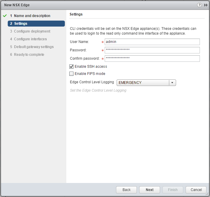
Click Next.
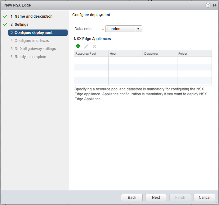
Click Add (+).
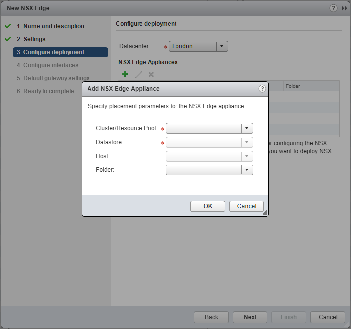
Select the appropriate Cluster/Resource Pool from the dropdown.
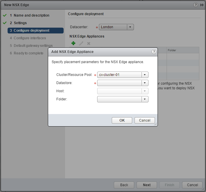
Select the appropriate Datastore from the dropdown.
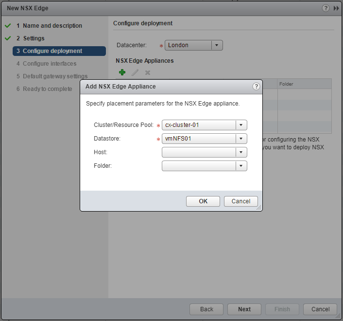
Click OK.
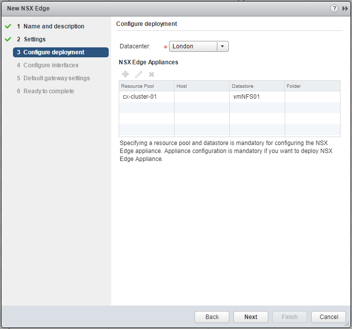
Click Next.
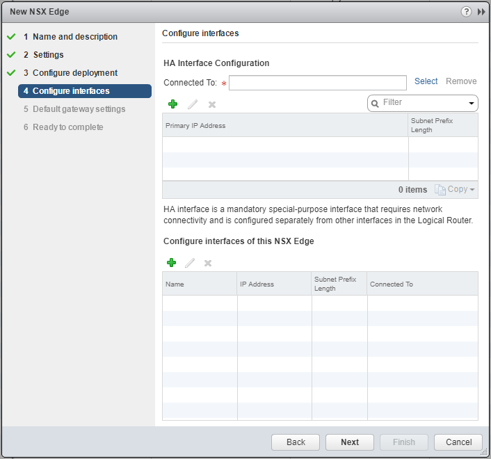
At HA Interface Configuration, click Select.
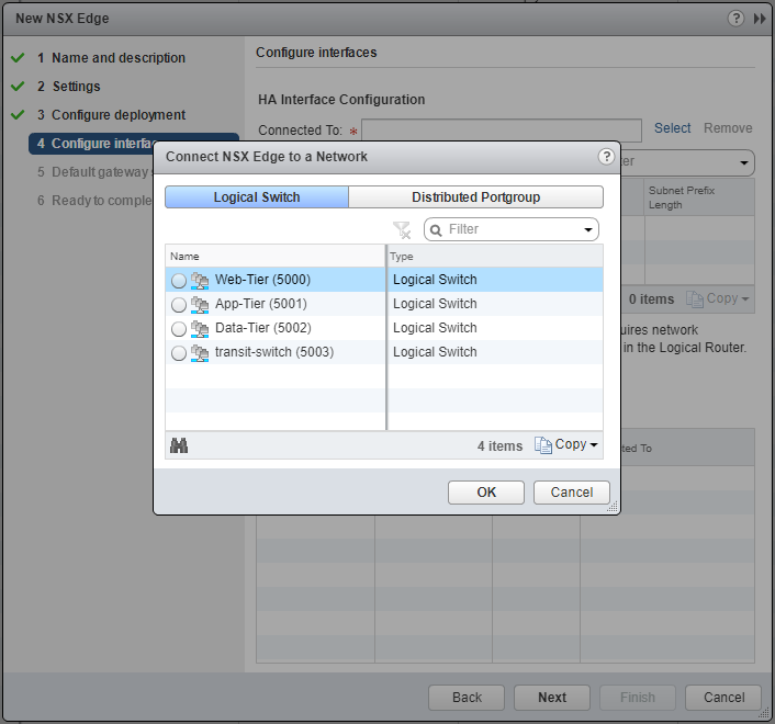
Select the appropriate network and click OK.

At HA Interface Configuration, click Add(+).
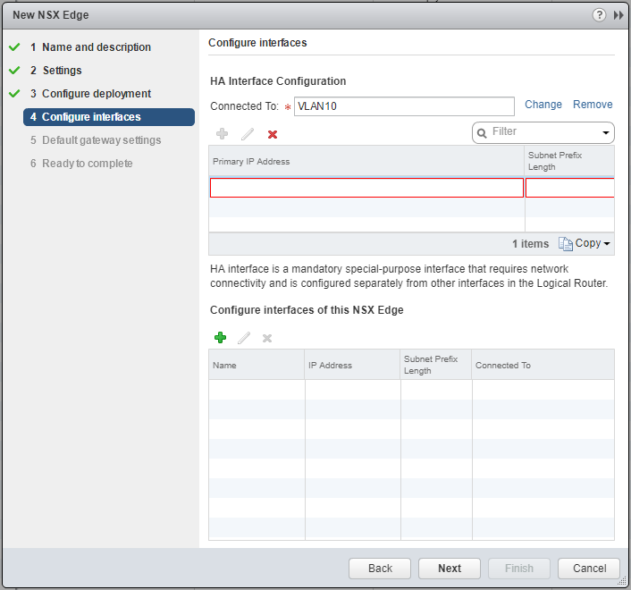
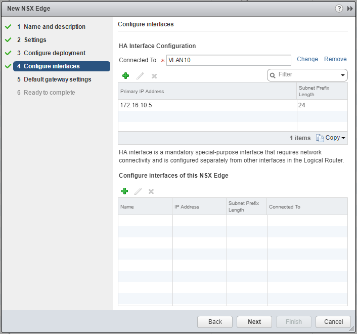
Enter the Primary IP Address and Subnet Prefix Length and click anywhere the window.
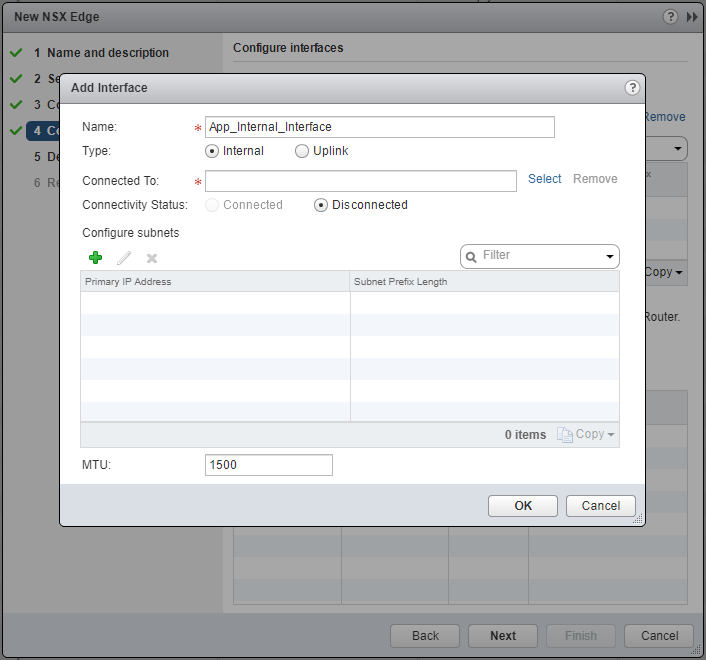
Under Configure interfaces of this NSX Edge, click Add(+).
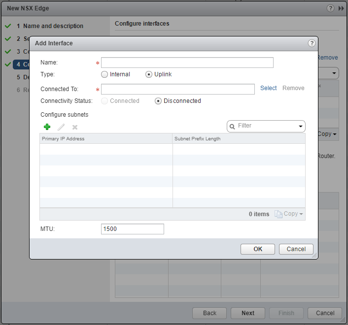
Enter the Name of the interface, and select either the Internal or Uplink option.
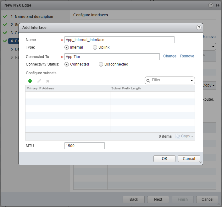
At Connected To click Select.
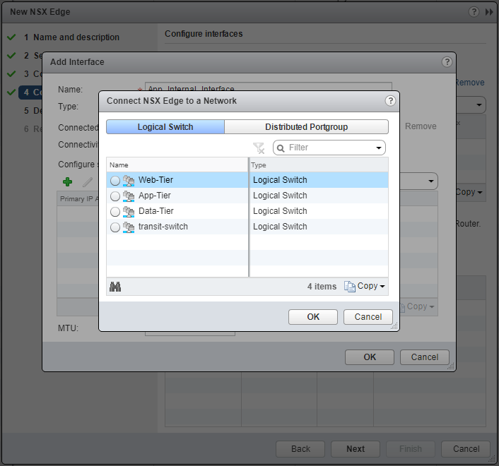
Select the appropriate Logical Switch and click OK.
At Configure subnets, click Add(+) and then add the Primary IP Address and Subnet Prefix Length.
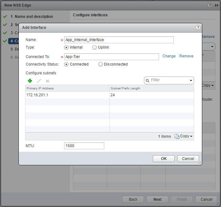
Click OK.
Note: Repeat the previous steps to add additional Internal and Uplink interfaces as required.
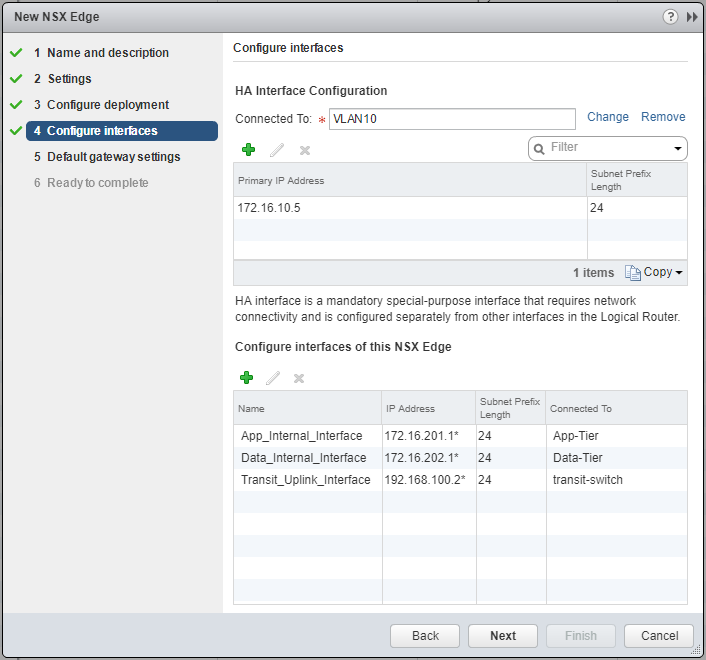
Click Next.
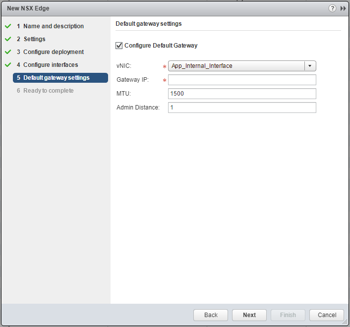
Select the appropriate interface from the vNIC dropdown and enter the Gateway IP address.

Click Next.
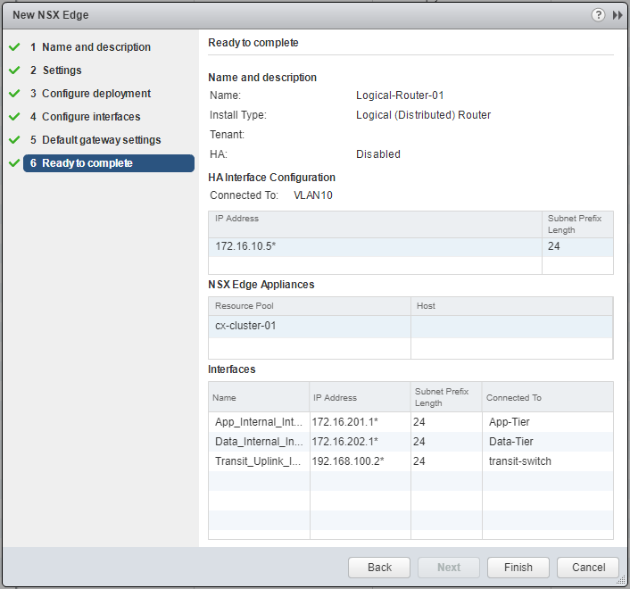
Click Finish.
Published on 31 July 2017 by Christopher Lewis. Words: 366. Reading Time: 2 mins.
- VCAP6-NV Deploy - Objective 2.2 - Configure and Manage Layer 2 Bridging ()
- VCAP6-NV Deploy - Objective 5.2 - Monitor a VMware NSX Implementation ()
- VCAP6-NV Deploy - Objective 3.1 - Configure and Manage Logical Load Balancing ()
- VCAP6-NV Deploy - Objective 2.3 - Configure and Manage Routing ()
- VCAP6-NV Deploy - Objective 5.3 - Configure and Manage Role Based Access Control ()
- Operating a Private Cloud - Part 3: Creating a Pricing Card in VMware Aria Automation
- Operating a Private Cloud - Part 2: Creating a Pricing Card in VMware Aria Operations
- Operating a Private Cloud - Part 1: Understanding Pricing Cards in VMware Aria
- Zero2Hero - Using Aria Automation to Deploy Multiple Machines with Multiple Disks - Part 5
- Zero2Hero - Using Aria Automation to Deploy Multiple Machines with Multiple Disks - Part 4